
Stress Corrosion Cracking of Stainless Steel
Grade 316L austenitic stainless steel is widely used by the oil and gas industry to handle sweet and mildly sour process fluids. Because of concerns about its resistance to chloride stress corrosion cracking (SCC), the alloy was limited to a maximum temperature of 60°C and 1 bar H2S in ISO 15156 part 3/ NACE MR 0175. In recent years data has been generated to support the use of 316L to higher temperatures, albeit with lower partial pressures of H2S. However, these limits are for resistance to sulphide stress corrosion cracking. Chloride SCC of 316L can occur in aerated solutions with only a few mg/L chloride at temperatures above ~60°C. Hence, when 316L is used for hot process pipes, it is important not to use it in areas where it can get splashed with water, or to provide adequate, waterproof insulation.
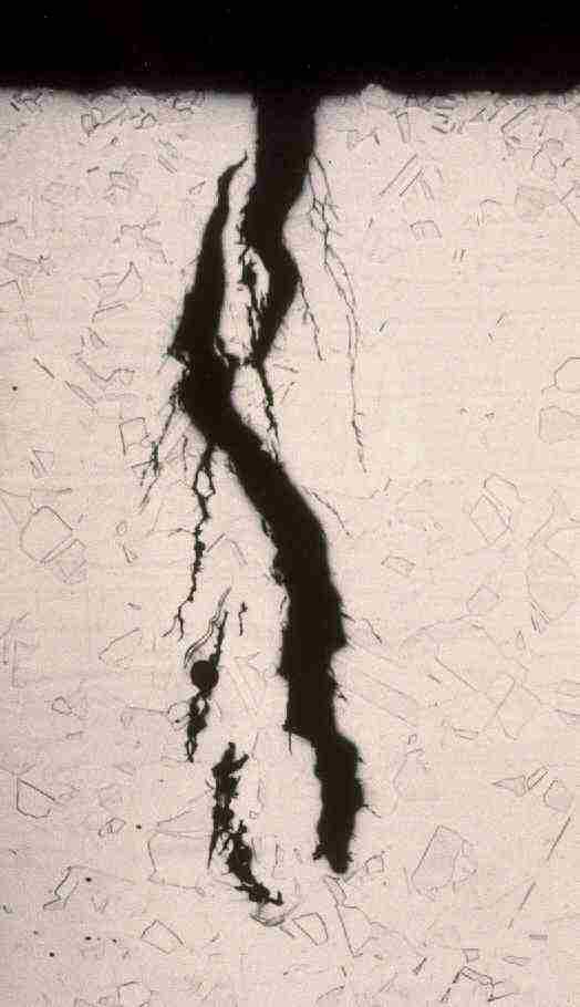
Chloride SCC of 316L stainless steel
Posted on: 7th August 2017
Carbon Steel in Seawater 2
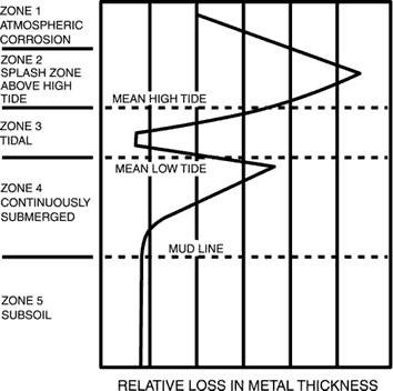
The corrosion rate of carbon steel in quiescent seawater is ~0.1mm/y, but the rate can vary markedly with position, relative to the mean high and low tide level (see below). Protection of a steel structure can be achieved by various means. Each corrosion zone shown below must be separately considered. Generally accepted methods to control corrosion are cathodic protection (CP), painting or coating, and sheathing.
The spray and splash zone above the mean high-tide level is the most severely attacked region because of continuous contact with highly aerated seawater, and the erosive effects of spray, waves, and tidal actions. Corrosion rates as high as 0.9 mm/y at Cook Inlet, Alaska, and 1.4 mm/y in the Gulf of Mexico have been observed. Cathodic protection in these zones is ineffective because of the lack of continuous contact with the seawater (the electrolyte), and thus no current flows between the metals for much of the time. Coatings need to be very robust as the conditions can be damaging. Sheathing in the forms of neoprene, other rubber coatings or nickel and copper alloys have been used successfully.
Corrosion rates for bare steel pilings, etc., also can be high at the position just below mean low tide and are caused by galvanic effects because of the different levels of aeration that occur in the tidal region. Corrosion can be controlled by CP systems because the area is continuously immersed.
Corrosion just above and below the mud line are both about 0.1mm/y, because the action of sulphate reducing bacteria in the mud provides analternative cathodic reaction to the reduction of dissolved oxygen, which is the cathodic reaction above the mud line.
Posted on: 21st July 2017
Carbon Steel in Seawater 1
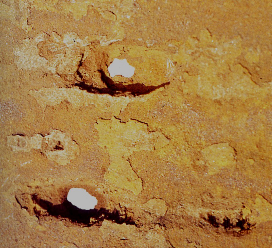
When using carbon steel in seawater without a coating or cathodic protection, it is common to use a corrosion allowance, say 3mm. However, this is making an assumption about the uniform corrosion rate of steel. In quiescent seawater it is about 0.1mm/y, rising to ~0.8mm/y at 3m/s flow velocity.
Even at low flow rates, the pitting of carbon steel in seawater is much faster than general corrosion, with typical rates of perforation of 2mm/y at 0.5m/s flow velocity. This is why carbon steel pipes carrying seawater usually perforate in 18 months to 2 years, depending on flow velocity, unless additional protective measures are used.
Posted on: 7th July 2017
Copper Alloys and MIC
Because copper is toxic to many life forms it is often assumed that copper and its alloys do not suffer from microbially influenced corrosion (MIC). This is not true and there are a number of ways that bacteria can affect the corrosion of copper alloys, and not all of them are detrimental.
In seawater, aluminium brass forms a protective film of hydrotalcite (Mg6Al2[OH16]CO3.4H2O), which is composed of a minor constituent of the alloy and of seawater. This film does not form in synthetic seawater, and it is produced because natural seawater contains bacteria that chelate the copper and zinc dissolving from the alloy, and preventing them from becoming incorporated into the protective film. This film adjusts its composition to buffer the pH at the metal surface and reduce metal dissolution.
Copper alloy corrosion can be greatly accelerated when sulphides are present, particularly in aerated waters. Sulphides are frequently generated by sulphate reducuing bacteria. These bacteria do not usually produce sulphide on copper alloy surfaces, but become active under deaerated conditions, for example, stagnant enclosed water. Hence the sulphide is often produced upstream of the copper alloys and the sulphide contacts them when flowing conditions resume.
Posted on: 21st June 2017
Pump Velocities
When calculating the water velocitiy in a centrifugal pump, it is common to calculate the rotation speed of the outer edge of the impeller and quote this as the maximum flow velocity. However, this gives far too high a velocity than actually occurs in service. This is because the water in this region is also moving, although not as fast as the impeller.
A more reliable way to calculate the water velocity seen by the pump materials is to recognize that most impellers have vanes that follow a logarithmic spiral (or close to it). The properties of this curve are that the flow velocity between the vanes is approximately constant, because as the cross sectional area between the vanes increases, the water is accelerating. Hence, the maximum water velocity can be calculated from the liquid flow from the impeller and the cross sectional area of the impeller at the circumference.
In many water pumps this velocity is 4 to 5 m/s and explains why nickel aluminium bronze works so well in this application, when it would not at the 10 - 20m/s velocity calculated from the rotation speed of the impeller circumference.
Posted on: 7th June 2017